Vibration Welding | Vibration welding of thermoplastics involves two pieces that are plasticized in the joint zone by means of friction and joined under pressure.

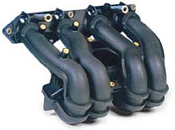
 | | Fig. 1 Air Intake Manifold Daimler | Strengths - Cost effective process
- Short cycle times
- Large batch sizes possible
- High mechanical load capacity

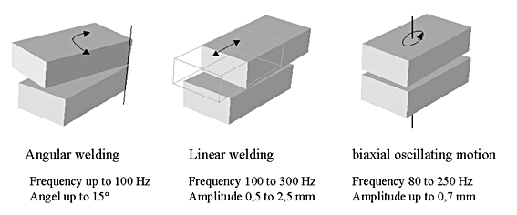
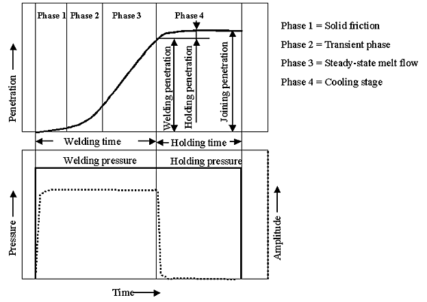
 | | Fig. 2 Basic possibilities of vibratory motion in the vibration welding process | In the vibration welding process two pieces are rubbed together under joining pressure according to the type of vibratory motion used. In process phase 1 solely solid friction prevails. Due to the generated heat, part of the joint area is already plasticized in phase 2. Phase 3 is the stationary melt formation phase in which the entire joint area is plasticized. The newly formed melt remains in a constant relationship to the melt squeezed out as a result of the joining pressure. The vibratory motion can be switched off in this phase. After the motion is switched off, the melt sinks as it cools down due to the hold pressure that is still applied.

 | | Fig. 3 Flow chart of a linear welding process | All LANXESS thermoplastics can be vibration-welded. Durethan KU2-2140/30 H2.0 resin is characterized by a significantly improved welding process window. As a result, for example, higher burst pressure can be achieved at air intake manifol

Application limits By means of vibration welding, tight welds are possible without any problem. The average cycle time is considerably shorter than 30 s. Due to the vibratory motion in one axis, only 2-dimensional joint contours are fundamentally possible. In the case of biaxial vibration work can only be carried out one-dimensionally. The joint geometry with a flash groove on both sides is quite large (> 10 mm width). The flash occurring is considerable due to the tolerance-related welding displacement. Therefore, sufficiently large flash grooves must be provided.
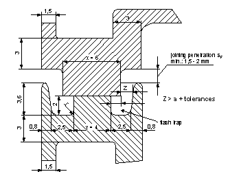
The weldline design depends on the component. A weldline that has proven effective in vibration welding plastic air intake manifolds will be described in the following. The clearance for the ejected melt should be at least 1.2 times the max. molten material.

 | | Fig. 4 Typical vibration weldline of an air intake manifold made of Durethan GF30 | Processing Recommended setting parameters

| Resin | Welding pressure | | Centrex ASA | 1 - 2 N/mm2 | | Durethan PA 6 and 66 | 0,5 - 3 N/mm2 | | Lustran ABS / Novodur | 1 - 2 N/mm2 | | Lustran SAN | 1 - 2 N/mm2 | | Pocan PBT | 1 - 4 N/mm2 | | Triax PA+ABS | 1 - 3 N/mm2 | The customary amplitude sizes for linear vibratory motion are between 0.6 - 0.9 mm and for biaxial motion from 0.4 - 0.7 mm.

Mold technology In vibration welding attention must be paid to the permissible mold weight in accordance with the machine size. The workpiece retainers must be adapted to the component contours in the seam area because there are deviations from the CAD data of the injection molds due to shrinkage and distortion. No moving parts (slide devices) should be inserted in the top mold because of the vibratory motion.
Vibration welding machines are usually driven by means of an electromagnetic vibration system.

| | | |

