|
|
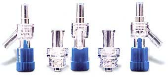
Ultrasonic Welding | The ultrasonic welding of thermoplastic parts involves plasticizing the join partners by deliberately converting ultrasonic energy into heat under pressure in the join zone. The geometry of the join zone plays a crucial part in the conversion of ultrasonic energy.

 | | Fig. 1 | Strengths - Cost-effective process
- Large batch-sizes are possible
- Very short cycle time

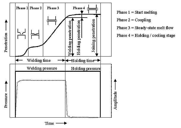
Ultrasonic welding involves transmitting sonic vibrations into a join part via a sonotrode. Precisely designed weldline geometry converts this ultrasonic energy into heat, in order to achieve the plastification of the join zone. The individual process steps are shown in the process diagram below.

 | | Fig. 2 Process diagram of the ultrasonic welding process using an energy director | Material All LANXESS thermoplastics can be welded with ultrasonics. Ultrasonic welding offers the advantage of very short cycle times; the pure welding time is well under 1 second. Within certain limits, 3-dimensional weldline contours are possible. The size of the join area is limited. Due to the energy output of the generator, join areas up to 1500 mm² are possible. Tight welds are easier to achieve with the shear joint geometry.
When semi-crystalline products are being welded, a higher energy consumption can be expected, which may require a higher output from the generator. Stray sonic beams can cause damage to components. Long, thin sections of components are particularly vulnerable to resonance behavior and internal vibration, and can break off or start to melt. High-frequency vibration movements cause the formation of fine fluff during welding.

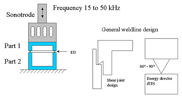
Component design  | | Fig. 3 Basic seam geometry in ultrasonic welding | In order to be able to convert ultrasonic energy effectively in the join zone, special weldline geometry has to be used: it consists of two basic variants with a large number of sub-variants. The distinguishing feature of so-called energy direction transmitter geometry is its efficient conversion of ultrasonic energy and its simple production. If the avoidance of leaks and the strength of the weldline are of particularly great importance, then shear joint geometry is preferable.
With ultrasonic welding, unlike other welding processes, there are many factors that can affect the result. The normal ultrasonic frequencies lie in the range between 15 and 40 KHz. The following amplitudes have proven their worth at 20 KHz:

| Centrex ASA and AES | 20 - 35 µm | | Durethan PA 6 and 66 | 30 - 50 µm | | Lustran ABS / Novodur | 20 - 30 µm | | Lustran SAN | 15 - 30 µm | | Pocan PBT and PET thermoplastic polyesters | 30 - 50 µm | | Triax ABS+PBT | 25 - 45 µm | Tooling A good, clean connection to the sonotrode is necessary to ensure a good conduction of sound into the component. It must therefore present the whole of its surface to the component. The clamping tool must prevent any lateral movement of the component.
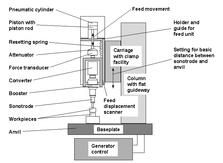
Ultrasonic welding machines are available on the market with pneumatic or electric drives. The basic construction principle is shown in the illustration below.

 | | Fig. 4 Basic construction of a pneumatic ultrasonic welding machine | | | |
 |
|
|
|
|