|
|
Thin-Wall Technology | Thin-wall technology is a recently developed and cost-effective plastic design technology. Using thin-wall technology not only saves material due to reduced wall-thickness, it also shortens cooling time which, in turn, helps optimize cycle time. Producing thin walls also results in material savings and miniaturization. The reduction of component thickness is limited by the following frame condition.

- melt flow behavior
- max. injection pressure
- component strength
- general reglementation (standards, legal regulations)

The above mentioned advantages can be achieved by:

- selecting suitable materials
- material knowledge
- strictly using rheological simulation progams
- suitable part design and tool design (figure)

 | | Fig. 1 Typical thin-wall parts | Strengths - weight savings
- reduced cooling time
- cost reduction
- miniaturization

In thin-wall technology, material properties are fully utilized from both the technical point of view, regarding production-related issues, and the processing point of view.

| | | Wall-thickness reaches the limits of process capabilities. |

Knowing the material including its mechanical and, in particular, rheological properties, thin-walled components can be produced by injection molding. In comparision to conventional design, material savings can be achieved allowing for the production of light-weight components. Two development trends can be recoginized:

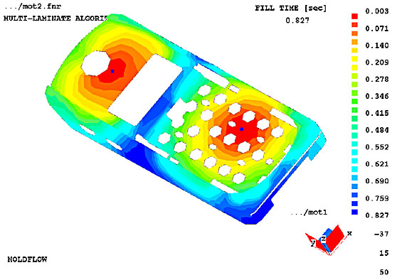 | | Fig. 2 Determination of the setting degree of a mobile phone case | 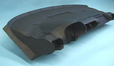 | | Fig. 3 Instrument panel, Plastic, wall-thickness 1.9 mm | 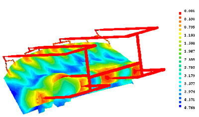 | | Fig. 4 Determination of the mold filling degree of an instrument panel | Both trends are based on the same intension: cost reductions. Still, their approach as to thin-wall parts is different.

Goals and reasons in favor of thin-wall technology: - cost reductions
- reduced cycle times
- weight savings
- miniaturization
- recycling

Measures to achieve these goals:

- selection of suitable materials
- suitable part design for plastic applications
- mold filling simulation including gating concept with the focus on filling pressure, pressure distribution and melt shear rate
- increasing tool rigidity with additional support and locking mechanism
- suitable demolding technology
- balanced gate concept

| | | Thin-wall technology: wall thickness is always depending on flow length. |

Thin-wall technology is limited by:

- reduced stiffness/component strength
- flowability of thermoplasic materials
- flowability of thermoplasic materials
- general reglementations by standards or legal regulations

In thin-wall technology, requirements have become more stringent regarding part design and processing compared to conventional injection molding processes. In this context, beside pressure, temperature and shear rate other process parameters are simulated and viewed in a special way. With extremly reduced wall thickness injection speed is the key to compensate temperature loss through the tool surface with increased shear of the melt.
Beside application-oriented criteria concerning material selection, Thin-Wall technology asks for special requirements summarized under "processing window". Usually all LANXESS thermoplastic materials can be used in thin-wall technology; in this regard, the flowability of thermoplastic materials are of great importance. LANXESS-Research has therefore committed itself to further improving flowability of LANXESS thermoplastic material. Durethan serves as an example of this development. (figure)

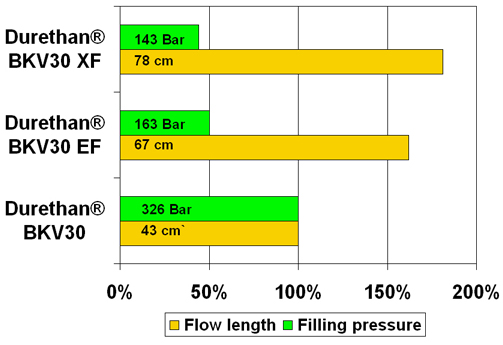 | | Fig. 5 Flowability of various Durethan grades | The loss of rigidity as a result of reduced wall thickness can be compensated using glass-filled materials. So far, glass filled plastics have only been used for technical applications; today, however, materials with the smal amount of 10% glas fillers are available in order to compensate the loss in rigidity. Using these materials in combination with a proper flow behavior, E-modulus and, consequently, rigidity can be increased by 100%.

Part design Reduced rigidity as a consequence of reduced wall thickness is usually compensated by using stiffening ribs. Unfavorable rib design, however, may result in sinkmarks visible on the outer surface. If excellent surface finish is requiredoptical an appropriate rib/wall thickness ratio is necessary. The rib/wall thickness ratio is about 1:2 for standard wall thicknesses using amorphous materials. Due to the high filling pressure in combination with minimized shrinkage the ratio can be reduced to 1:1. This strategy improves the demolding process for thin-wall structures, including ribs.
In contrast to standard injection molding, there are further differences in thin-wall technology regarding component design:

- demolding draft angle
The draft angle must be increased by a value between 0.5 and 1° depending on surface structure and depth of the texture. - shrinkage
The level of shrinkage depends on the material used and is to a great extent determined by the filling pressure and wall thickness. Shrinkage is reduced by up to 50% in case of thin-wall parts with wall-thicknesses of about 1 mm.

Gate concept The gate concept is of great importance in thin-wall technology. The processing window of the plastic largely depends on type, position and geometry with regard to the production of high-quality articles. Therefore, we also need a gate system designed by means of rheological filling simulation for thin-wall technology.
Aside from temperature and shear, the following parameters must be observed:

- flow path
- filling volume
- pressure
- pressure distribution

Demolding technology The partially reduced sectional stiffness of the part in combination with a low shrinkage usually require a sophisticated demolding system. The ejectors must be positioned as to absorb highest friction forces and flexural moments which usually occur in the area of the ribs and screw heads during demolding process. (figure)

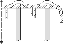 | | Fig. 6 Unfavorable demolding design: deflection of component (figure) | 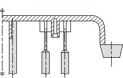 | | Fig. 7 Favorable demolding design | Tool rigidity High injection pressures occur when the mold is being filled. In thin-wall technology, those pressures may considerably exceed standard levels. This requires the employment of high-rigidity tools. In standard injection molding with a wall thickness of 3mm, injection pressures of up to 100 MPa must be applied to produce components. The production of cellular phones covers, featuring a wall thickness of about 1.5mm, requires filling pressures of about 140 MPa. At wall thicknesses below 1.0mm, however, filling pressures of up to 250 MPa are usual. Actions to increase tool rigidity:

- tight toleranced inserts
- reduced number of inserts and mold plates
- interlocked cavities
- ejector frames /-slats
- additional support in the ejection area
- tight toletight tolerances of pressure-loaded slidesrances of pressure-loaded slides

Mold temperature control The most important driver for thin-wall technology is the reduced cycle time. In order to reach an optimum, the cooling system must be designed as to evenly conduct melt heat out of the mold within a short time. Further contents will be presented separately.

Processing Standard tool and melt temperatures can also be applied when dealing with thin-wall parts. In order to reduce the filling pressure, however, it is usually recommended to increase melt temperature as far as possible within an acceptable range. In connection with a long melt residence time in the barrel, this can lead to critical material reduction. Under "machines" this item will be further discussed. In order to avoid freezing effects during the filling process, the injection time is rather short. In case of cellular phone covers, standard injection times are <0.5s.
Most important items to be considered when selecting injection molding units are low shot weight in combination with high pressure demands. Especially when dealing with small-size components this leads to the employment of special injetion molding units which consist of a barrel unit with a small screw diameter and a clamping unit featuring a high clamping force. Small screw diameters ensure both, high injection pressures and short melt residence times. High clamping forces, however, ensure that the cavity cannot be opened during the filling process and the risk of flash is minimized.

| | |
 |
|
|
|
|